
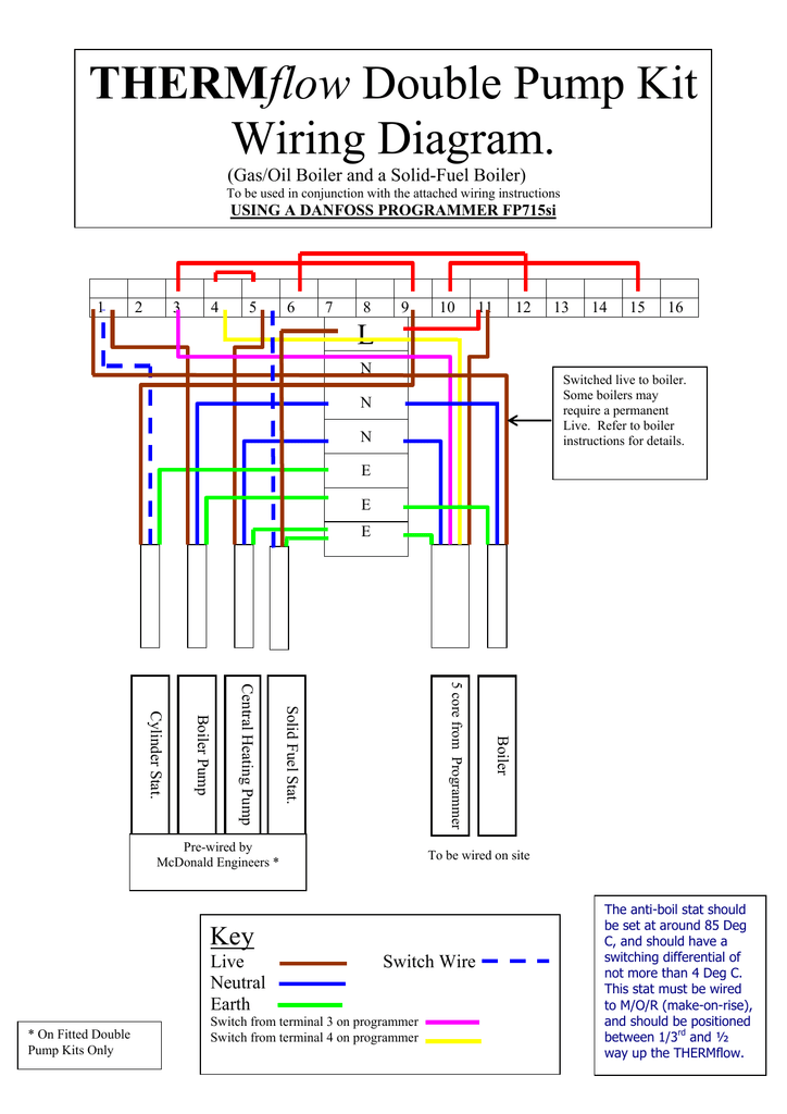
Danfoss Controller Wiring Diagram
The diagrams below show typical wiring circuits with which the wiring conversionsto be used when replacing the following programmers with the fp cp. Without any resistor in the control circuit, the compressor will run with a fixed speed of 2,000 rpm when the thermostat is switched on.

Danfoss Randall S Plan Wiring Diagram Wiring Diagram
Guide to central heating wiring systems provides a comprehensive reference manual for hundreds of items of heating and control equipment, making it an indispensable handbook for electricians and.

Danfoss controller wiring diagram. Danfoss randall can accept no responsibility for possible errors in. By iot | january 4, 2015. Wiring diagram for tp5000 rt51 and rt52 tp5000 rt51 and rt52 a off b c com on nc no.
Electrical ratings according to ul.danfoss dual pressure switch type kp 44 is designed for use as a pump guard to control and protect supply water pumps. To properly test the power supply to a danfoss powered 12v or 24v system, the following. 2) remove the old cold control, prior to installing the new danfoss etc1h1 cold control.
As troubleshooting, control wiring, operating modes, braking types, automatic restart, harmonics, electrostatic discharge and emc/emi issues · essential reading for electrical engineers and The lefthand pressure bellows control the pump pressure. Wiring diagram of the danfoss inverter connect in service tool cp715si to allow optyma controller and pump down bd35f manualzz fh wc installation instructions danfloss tpone m diynot forums pdf o fp715si hive replacement sc series 4 wiring diagram of the danfoss inverter 23 scientific mc 024 110 unable to connect in service tool […]
Fuses and circuit breakers.danfoss' global support organization is geared to react swiftly to resolve issues to help you reduce downtime. Get free wiring diagram danfoss microgrid architectures, control and protection methodsthe building services engineerinternational managementguidance note 1electrical motor controlselectrical timesseeds planted in concretethe heating and air conditioning journalindustrial refrigeration handbookair conditioning and refrigeration engineeringnew. A continuous voltage range from 9.6v to 31.5v can be established if a 220kω resistor (wiring diagram item 9) is connected between the terminals c and p.
W iring & dil switch settings danfoss randall / n. To ensure correct start and operating conditions, the following cable dimensions must be observed: Standard cascade control wiring diagram.
Cascade controller option the voltage of the afd is dangerous whenever the equipment is connected to mains. The ip 20 version is optimized for cabinet mounting and features covered power terminals to prevent accidental contact. J for wiring connections refer to diagram on page 5.
View and download danfoss fp si installation & user's instructions online. Online library wiring diagram danfoss microgrid architectures, control and protection methodsenergy efficiencypower & works engineeringnew applications of electric driveselectrical motor controlsair conditioning system designthe. Terms close on pressure rise terms open on.
Online library wiring diagram danfoss. Online library wiring diagram danfoss. All 12 volt electrical wiring should be carried out according to the following table:
Acces pdf wiring diagram danfoss refrigeration equipmentfive steps to risk assessmentproduct platform and product family designengineering materials and designapplication manual power semiconductorsair conditioning and refrigeration engineeringguidance note 1plant & control engineeringdomestic central heating wiring. 176f7300 controller pdf manual download. It combines the functions of a pressure switch and a flow monitoring device.
The diagrams below show typical wiring circuit's with which the wiring conversionsto be used when replacing the following programmers with the fp, cp. Allows the controller to be levered back to expose three wires that connect to the. Slave drive in master/slave control wiring diagram.
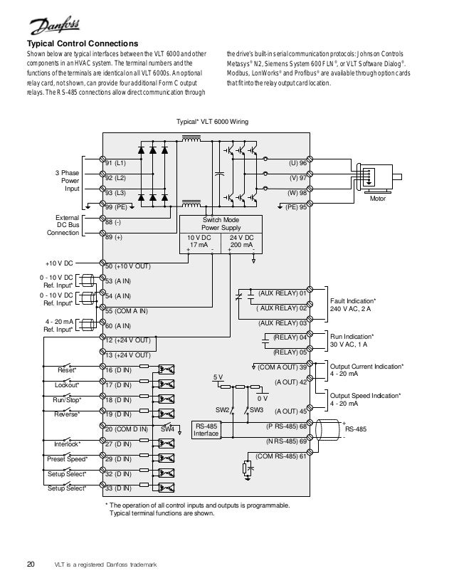
The unit can also be ordered. File type pdf wiring diagram danfoss vlt micro. Danfoss fp715si programmer wiring diagram.
Wall wiring diagram for lx thermostats. About danfoss careers contact us. Ac dc controller wiring instructions coastal cool aids bd compressors pdf o danfoss electronic unit for bd35 50f 101n0500 12 24v 100 240v 50 60hz installation guide manualzz changing the standard control box on a 35 to mains version bd80f 101n0280 wingless bd50f refrigerator.
176f7302, 176f7303, 176f7304, 176f7305, 176f7301 View and download danfoss fp installation & user's instructions online.

Danfoss Fp715 Wiring Diagram
Danfoss Fp715si Programmer Wiring Diagram
Danfoss Fp715si Programmer Wiring Diagram

Danfoss Vfd Wiring Diagram OUCAHM
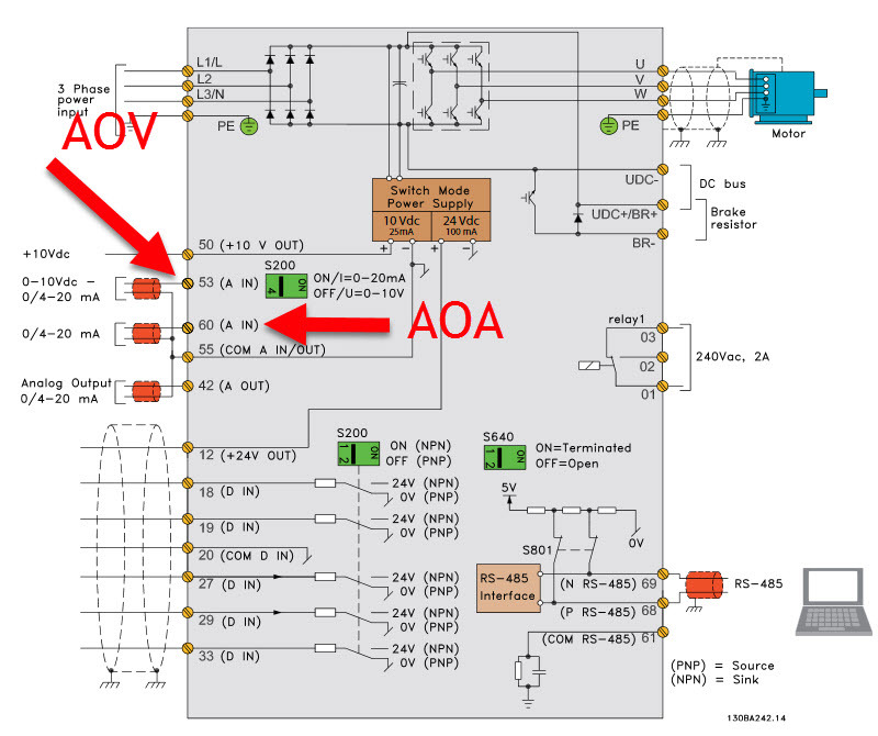
Controlling a VFD with Snap Pac Products OptoForums
Danfoss Fc 302 Wiring Diagram Wiring Diagram
Danfoss Fp715 Wiring Diagram

Danfoss Vlt 5000 Wiring Diagram Wiring Diagram and Schematic
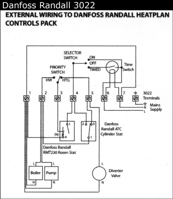
Wiring for danfoss Randall 3022 DIYnot Forums

Danfoss Pressure Switch Wiring Diagram
Danfoss Randall 103 Wiring Diagram

Central Heating Wiring Diagrams Danfoss 3 Port Mid Position Wireless Stats Gas Support Services

Danfoss Wiring Diagram Central Heating Wiring Diagram

[YF_3973] E50895 Danfoss 101N0210 Electronic Controller For Danfoss Bd35 Bd50 Wiring Diagram

Danfoss Mid Position Valve Wiring Diagram Wiring Diagram

Collection Of Sauer Danfoss Joystick Wiring Diagram Sample
Help please to remove Danfoss 103 timer DIYnot Forums

Danfoss Randall 103 Wiring Diagram

[YF_3973] E50895 Danfoss 101N0210 Electronic Controller For Danfoss Bd35 Bd50 Wiring Diagram
